
In a recent study published in the journal Energies, researchers from Canada developed a 35 GHz microwave frequency-based, low-cost and compact wireless power transmission system for a 22-kW unmanned aerial vehicle (UAV).

Study: Design and Analysis of a 35 GHz Rectenna System for Wireless Power Transfer to an Unmanned Air Vehicle. Image Credit: Anton Kudelin/Shutterstock.com
The optimized size of the transmitting and receiving system was 108 m2 and 90 m2, respectively. The linearly polarized rectangular microstrip patch antenna array demonstrated a high gain, high directivity, and high efficiency of 13.4 dBi, 14 dBi, and 85%, respectively. Additionally, the radio frequency (RF)-based rectifying receiving antenna (rectenna) system had an energy conversion efficiency of 80% for an RF input range of 9-18 dBm, and a DC output voltage of 3.5 V.
Wireless Power Transmission System
Wireless power transmission system (WPTS) is an on-demand area of research for cost-effective long flight electric UAVs. Electric UAVs with microwave power transmission systems (MPTS) have achieved an efficiency of up to 95%, whereas gasoline-based aircraft have an efficiency of 18-23%. Additionally, without any requirement of onboard energy storage systems, these e-UAVs are lightweight, quieter, and more reliable.
The wireless MPTS (WMPTS) consists of two sections i.e. a transmission antenna (Tx) and a receiving antenna or rectenna (Rx). The mechanism involves the conversion of DC power to microwave power using a microwave oscillator (i.e. magnetron or klystron) in Tx, which radiates in a Gaussian beamforming way towards the Rx through the free space followed by reconversion to DC voltage.
Furthermore, to increase the power gain at the rectenna side, different designs of rectennas are employed in WMPTS viz. spiral antennas, dipole, microstrip patch, and co-planer patch antennas. Moreover, to compensate for the low gain of a single antenna, an array of micro-antennas supplying more RF power is used in high frequency and the millimeter-wave range.
The most commonly used millimeter-wave antennas are 2.45 GHz and 5.8 GHz, whereas the commonly used high-frequency antennas are 24 GHz, 35 GHz, and 94 GHz. For long-distance transmission, high frequencies antennas reduce the size, cost, and power loss due to atmospheric absorption.
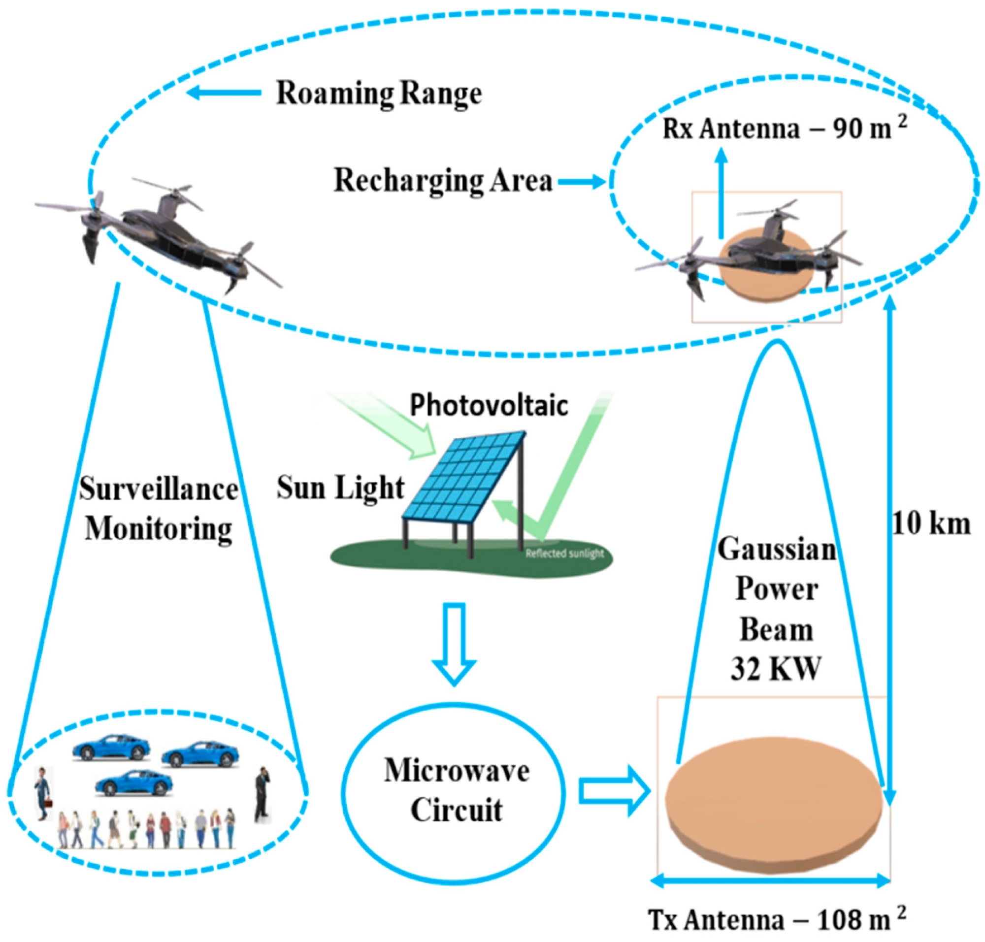
Proposed system architecture for microwave wireless power transmission. Image Credit: Hoque, M et al., Energies
About the Study
In this study, researchers set up a WMPTS for a 22-kW electrical propeller of a UAV. The system consisted of a photovoltaic array that collected a 160 kW of solar insolation at a power density of 1000 W/m2 produced a DC power of 40 kW at 25% conversion efficiency.
Further, the DC power was converted to microwave with a power of 32 kW at an efficiency of 80% in a microstrip patch Tx. Considering the atmospheric power loss, conversion efficiency at the rectenna end, and effective transmission distance up to 10 km, the 32-kW microwave transmitted to the 22-kW UAV provided smooth and uninterrupted service.
Subsequently, they measured the optimized size of Tx and Rx using the power transmission and receiving capacity of both antennas. For 32-kW capacity Tx, the required power density was 300 W/m2, which gave an area of 108 m2, whereas, for Rx with 27 kW RF power, the area was 90 m2. The rectenna was comprised of an antenna, a voltage doubler-oriented diode, a matching circuit, and a resistive load of 1500 Ω connected to the end of the circuit to collect the DC power.
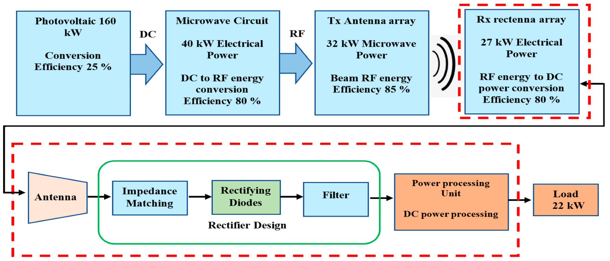
Microwave power transmission block diagram. Image Credit: Hoque, M et al., Energies
Observations
The surface current flow of a 4 x 2 patch Tx antenna array was linearly polarized with a reflection coefficient value of -33 dB, which was suitable for point-to-point power transfer at 35 GHz frequency. The radiation pattern of the Tx antenna array revealed that the energy passing through the main lobe had the maximum energy with the highest gain and directivity. The gain and directivity at 0 degrees of the microstrip patch Tx antenna array were 13.4 dBi and 14 dBi, respectively, whereas for the side lobes they were less than -11 dBi.
The rectifying nonlinear circuit simulation performed with a 10 dBm input RF power and 35 GHz frequency in an advanced design system (ADS) harmonics balance (HB) simulator showed that the maximum output DC power of 0.0065 watt was obtained at 3.1 V voltage across the 1500 Ω load resistance.
Furthermore, the impedance of the rectifying circuit was matched at a 50 Ω load resistance based on the variation with frequency. The rectenna without impedance matching (IM) had a maximum RF-to-DC conversion efficiency of 82% at 19 dBm, whereas with IM it had a similar efficiency above 80% between RF input power range of 9 to 18 dBm.
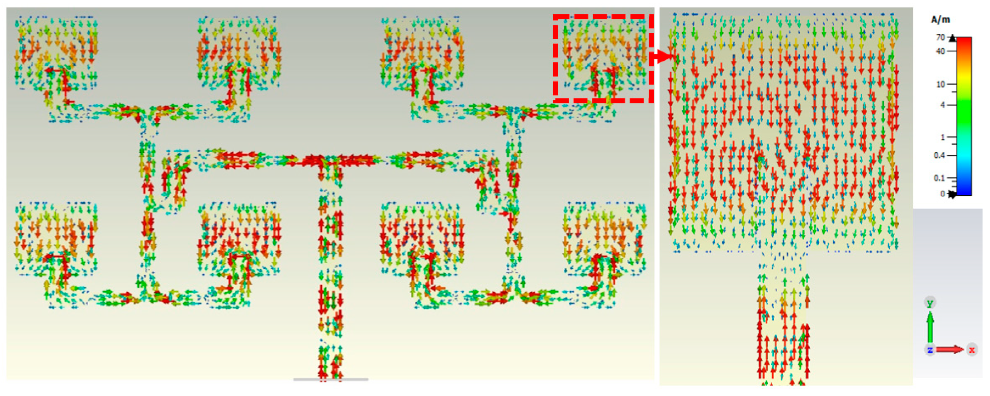
Surface currents plot of the 4 × 2 patch antenna array at 35 GHz. Image Credit: Hoque, M et al., Energies
Conclusions
In this study, researchers designed the critical architecture of 35 GHz frequency operated WMPTS for a 22-kW electrical UAV with an operational range up to 10 km. They incorporated 160-kW solar insolation collecting photovoltaic array, a microstrip patch Tx antenna with a capacity of 32 kW, and a voltage doubler diode-oriented Rx rectenna with an optimum load resistance of 1500 Ω.
The rectenna system had an energy conversion efficiency of more than 80% for an RF input range of 9-18 dBm, and a DC output voltage of 3.1 V. Furthermore, the optimized size of both antennas was 108 m2 and 90 m2, respectively.
Reference
Hoque, M., Kumar, D., Audet, Y., Savaria, Y., Design and Analysis of a 35 GHz Rectenna System for Wireless Power Transfer to an Unmanned Air Vehicle. Energies, 2022, 15, 320. https://www.mdpi.com/1996-1073/15/1/320